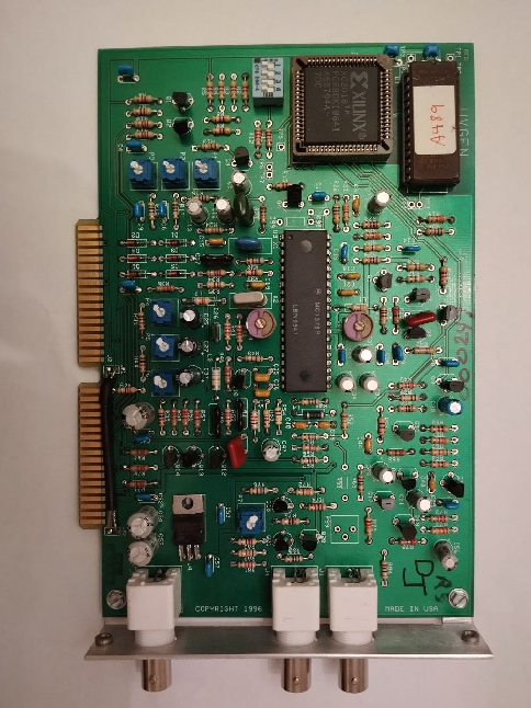
I bought this device on eBay and decided to make a replica of it.
More info coming soon.
I bought this device on eBay and decided to make a replica of it.
More info coming soon.

This post will be extended and improved while there is more info
As we sold many Digifiz Replica units on behalf of Duplux Production (https://www.instagram.com/duplux_production/) there are many common questions and corresponding answers should be. There will be some more info regarding the device.
As a Russian development, the original page of Digifiz Replica is on the Russian social network VK, here:
Also, I’ve created a Telegram page of Digifiz Replica some time ago:
Currently, here is an official Manual for Digifiz Replica on English:
UltiSID is released publicly and is now tested:
https://github.com/Sgw32/UltiSID
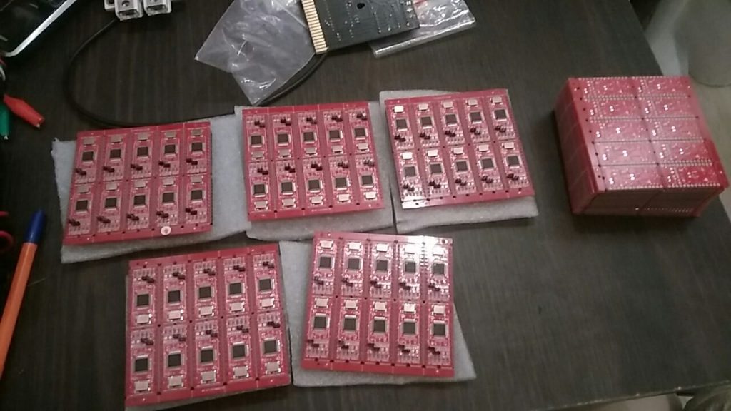
You can also order PCBs almost assembled using JLCPCB order files provided in the repository.
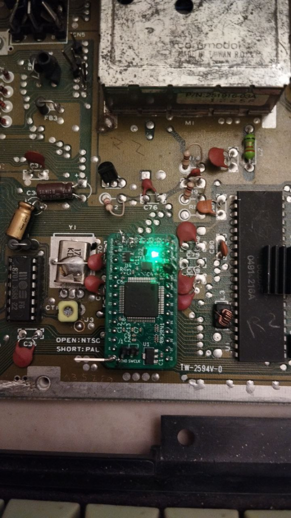
New UltiSID is highly inspired by Kung Fu Flash – and commonly, it is a Kung Fu Flash with a special firmware(Kung Fu SID, included as a submodule)
Video:
https://youtube.com/shorts/YMMjhMZqSjQ?feature=share – small video of new hardware and software working on a real C64.
By the way, I have 4 extra chips and I can send/sell them somewhere if someone wants to check them out.
As it was declared initially, UltiSID is completely free and open-source even for commercial purposes (GPLv3 license)
I will be happy if someone will improve the project or add some new functions to it. It still lacks paddles, but new hardware supports it.
As well, there is an OpAmp on output cascade, and output is completely generated by DAC, not PWM as on SwinSID – which ensures smooth and good generation of sound. I still need some optimization of code.
There are no hard flaws as it was before on the previous revision of the hardware. It processes data and it is possible to read it back, it works stable.
I would also be happy for any donation:
PayPal is unfortunately banned in Russia, as Russia resident I am unable to use it, even if I’m not in Russia actually(as it is)
0xeDc17cb23241eACe19DF3617291aa7d2d92E62DC – USDT/ETH ERC20
TKSPmVWoCgQky8umDUcR7oivJKNzAXueSB – USDT TRC20
0x77c411fdedc72b034432571ae9aee10330b72d6c – USDT BSC20
https://www.cgtrader.com/sgw32 – or buy something here(my 3d models of C64 for 3d printing)

XGpro T48 is a better version and is available here:
Gotek can be modded to add I2C display and buzzer.
Most of new revisions come with STM32 clone – AT32, can be flashed using USB cable.
http://alii.pub/6i5kny – SNES joystick
http://alii.pub/6i5k01 Atari-compatible joystick
This joystick will help to work on Commodore 64/Amiga/Atari machines, but it can be rewired for any other machine (MSX, ZX Spectrum).
This thing is very useful if you want to have a good quality of your image and use your primary monitor while working with retro computer. Personally I’ve tested it on Commodore Amiga.
http://alii.pub/6i5k9d – GBSC
http://alii.pub/6i5k9y – GBS8200
http://alii.pub/6i5lbh – Anycubic I3 Mega X
https://anycubic3dprinter.aliexpress.ru/store/721071?spm=a2g2w.detail.0.0.4dca54000tzw6c Anycubic Store
SCART can contain composite and RGB signals. This converter supports RGB format, so provides better quality.
68000 – microprocessor for Amiga, XC68000, Sega and others https://alii.pub/6rc8dc
68030 – microprocessor for many expensive Amiga accelerators https://alii.pub/6rc8e4
MOS 6502 – microprocessor for dozens of retro computers https://alii.pub/6rc8eb
YMF262 – OPL3 sound chip, produces SEGA-like music, and other FM https://alii.pub/6rc8ei
YAC512 – necessary component for YMF262 https://alii.pub/6rc8ew
I8086 – https://alii.pub/6rc8f3
KC89C72 – AY3-8910 sound chip functional analog https://alii.pub/6rc8fa
200x small radial capacitor pack https://alii.pub/6rc8fo
SMD capacitors https://alii.pub/6rc8g2
https://aliexpress.ru/item/4000762474316.html – Atari Jaguar
https://aliexpress.ru/item/32907768028.html – Sega Genesis/MD
https://aliexpress.ru/item/1005003424443171.html – NES cartridge(with games)
https://aliexpress.ru/item/1005002993055946.html – EEPROM eraser
https://aliexpress.ru/item/32996311620.html – 27C512
https://aliexpress.ru/item/4000702190607.html – 27C040
https://aliexpress.ru/item/1005003078637234.html -27C020
https://aliexpress.ru/item/1005001882853500.html – 27C32https://aliexpress.ru/item/1005004613641886.html – W27C020
Advertising/Реклама.
https://vk.com/sgw32
In this tutorial, I’ve used information from http://www.tolaemon.com/nss/ as well as my own experience for testing.
You’ll not only know how to assemble & flash SwinSIDs, but how to do it almost automatically.
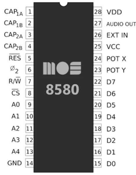
SwinSID is a microcontroller-based clone of the SID, the audio chip used in nearly all 8-bit Commodore computers in the 80s, and later in some chiptune synths like SIDStation. The original SID ( Sound Interface Device) was designed by the engineer Robert Yannes and produced by MOS Technology under the names MOS 6581 and MOS 8580 from the early 80’s to the early 90s. Despite the production of the original SIDs stopped years ago, you still can find spare units of unknown origin on some internet sales sites, but they are very expensive and usually have some of their parts damaged ( it is not strange to find units with malfunctioning filters or oscillators ).
Pinout of SID(and SwinSID too):
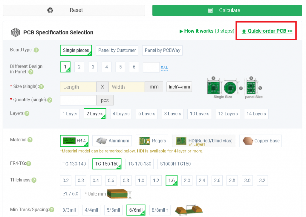
Here we’ll order boards that they will become partly(or fully) assembled.
To order fully assembled boards I do prefer PCBWay (use https://pcbway.com/g/Cc53D7), however you can use any other manufacturer.
Select necessary board number and select color of boards:
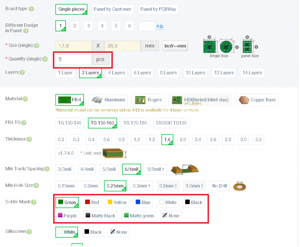
Turn on assembly service, enter necessary amount of boards and click “save to cart”, after that, you’ll be requested to update BOM, Pick and Place and gerber files.
Here they are(for full assembly):
Here they are(for manual header soldering, part assembly):
PCBWay accepts ordinary debit cards, PayPal and wire transfer. It is also possible to order for a company, they provide all the necessary documents.
Shipping using E-packet takes almost one month to Europe and USA(almost everywhere)
In Europe you can pay VAT while the order and receive items with simplified customs clearance.
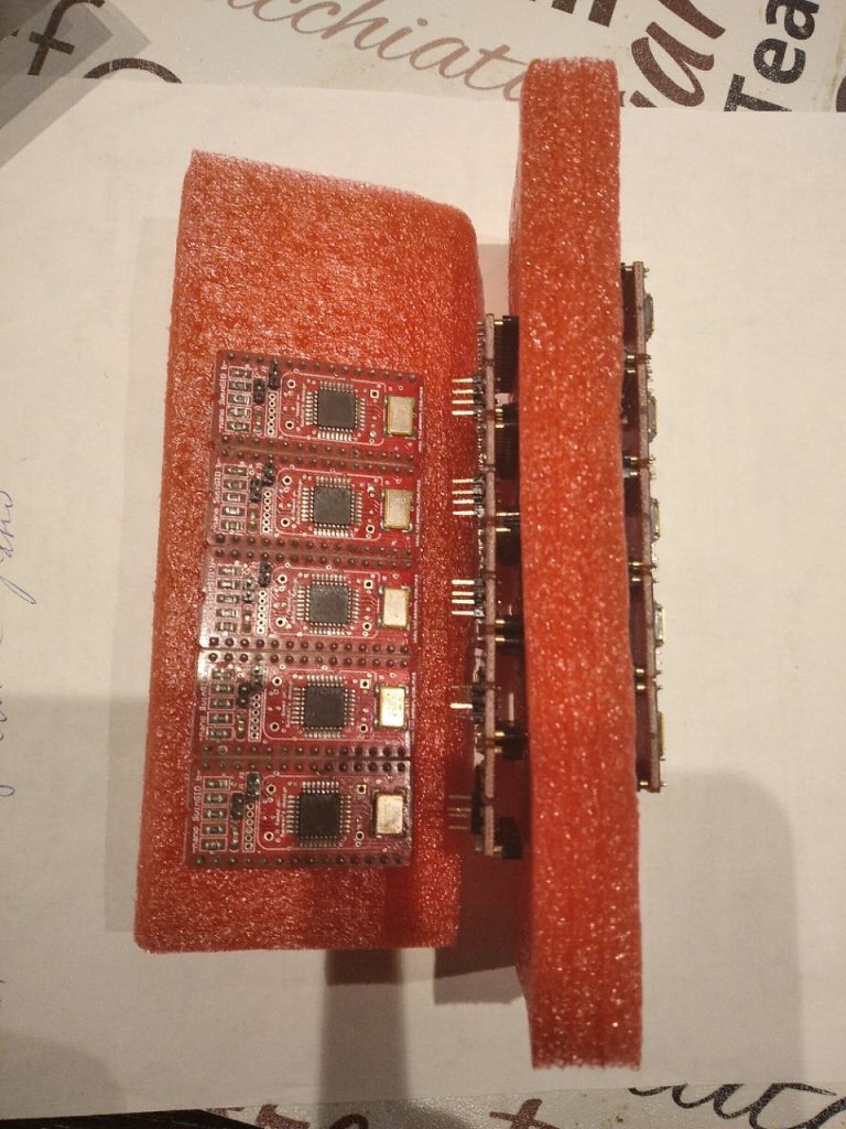
If you’ve ordered boards without DIP assembly, you’ll need 2.54 round gold-plated headers:
You can buy them here: Aliexpress headers
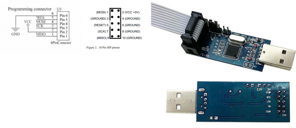
Necessary tools for flashing: USBASP Cable + adapter
Socket for USBASP: USBASP wires
Now, you need to make an adapter for flashing using USBASP.
Please connect lines 5V, MOSI, MISO, SCK, RST, GND to the corresponding pins on the bottom of USBASP.
Now, please download the flashing pack (for Windows, but you can adopt BAT file for Linux too) :
Insert to C64 socket, boot up (you’ll hear a “ping” sound)
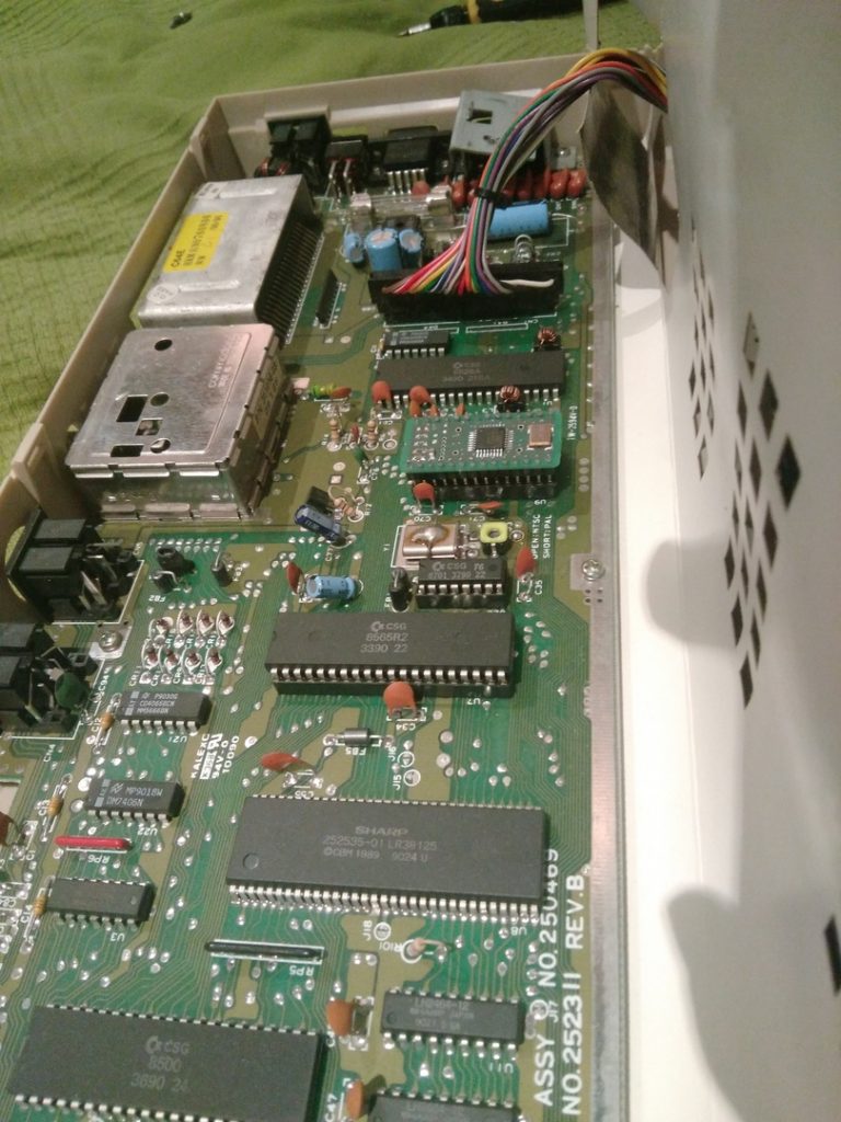
Try to load some music. If you’ve followed the instruction, you’ll hear the sound. Good luck!
Now our website supports crypto payments (and not only Place Order option).


To order, you can use BTC, ETH, LTC for payments.
We support Easypay and Metamask platforms, so you can use your favorite wallet to buy goods from our store.
WordPress and Woocommerce succesfully updated to 5.4.2 – even more secure and cutting-edge.
Hello!
Several updates and news:
We’ve switched to HTTPS protocol for our website, so it is much more secure than before.
During COVID-19 we keep dispatching parcels, however, Russian Post is keeping parcels at Russian border because there are very few airplanes.
Domestic shipping works very well.
Upcoming products: Amiga boards, Synths, RF-boards, High Voltage boards, some new cartridges for C64.
Best regards,
PHOL-LABS team
Under the name /dev/retro we had several exhibition in Moscow schools in 2019…
The exhibition was a presentation of computers and we allowed people to use them, play games on it
Here are the photos how it was: